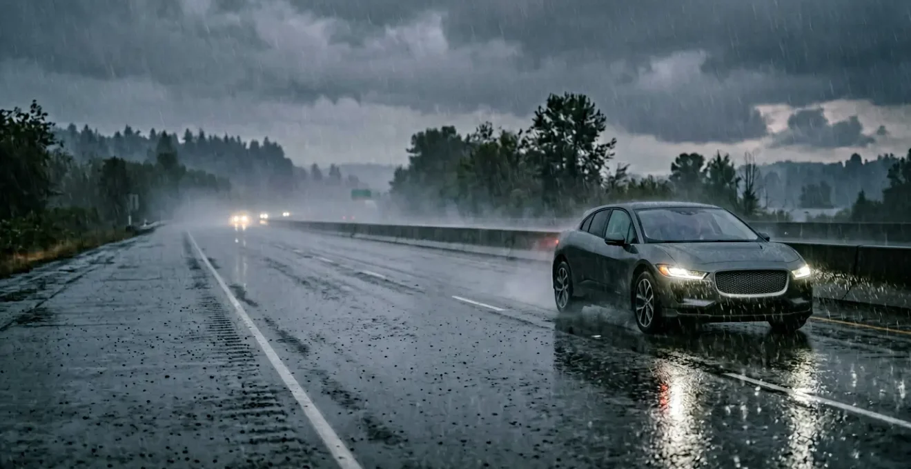
While radar’s fundamental physics give it an inherent advantage, the critical safety determinant in adverse weather is not the sensor type alone, but the system’s quantifiable performance degradation under specific environmental conditions.
- LiDAR’s range and data quality plummet in heavy precipitation, creating dangerous sensor blind spots and false positives that can compromise system safety.
- True system robustness depends on a meticulously defined and validated Operational Design Domain (ODD) that accounts for these physical limitations.
Recommendation: Investors and buyers must scrutinize a system’s ODD and its validation process for all-weather operation, not just the hardware specifications on a datasheet.
The promise of autonomous driving often conjures images of effortless travel, a vehicle navigating complex scenarios with superhuman precision. Yet, for any human driver, a sudden downpour is a signal to increase focus, slow down, and heighten awareness. This reality exposes a critical challenge for autonomous systems: can they perceive the world reliably when visibility drops? The debate often simplifies to a contest between LiDAR and Radar, with the common refrain being that radar’s radio waves handle rain better than LiDAR’s light pulses.
This oversimplification, however, is dangerously incomplete from an engineering perspective. The pivotal question is not merely *which* sensor is better, but *how* and *at what threshold* a sensor system’s performance degrades. A system’s safety is not defined by its peak performance in ideal conditions, but by its predictable behavior at the edge of its capabilities. The true measure of an autonomous system’s maturity lies in its Operational Design Domain (ODD)—the specific set of conditions under which it is designed to function safely.
This analysis moves beyond the surface-level debate to dissect the physics of sensor failure in heavy rain. We will explore the quantifiable impact of precipitation on LiDAR data, the engineering challenges of durability and maintenance, the threat of environmental interference, and the critical importance of system calibration. Understanding these failure modes is essential for any tech-savvy buyer or investor seeking to evaluate the true all-weather viability of an autonomous driving platform.
This article provides an engineer’s perspective on the critical factors that determine sensor safety and reliability in the real world. The following sections break down the specific challenges and considerations that define a robust autonomous perception system.
Summary: Analyzing Sensor Performance in Adverse Weather
- Why Low-Resolution LiDAR Misses Small Obstacles at Highway Speeds?
- How to Clean LiDAR Sensors Without Scratching the Delicate Lens?
- Solid-State vs. Spinning LiDAR: Which Is More Durable for Consumer Cars?
- The Sun Glare Angle That Blinds LiDAR and Causes Sudden Stops
- Where to Mount Aftermarket Sensors for Maximum Field of View?
- The Investment Mistake That Could Render Your Transport Logistics Obsolete in 10 Years
- V2I Communication: How Do Smart Signs « Talk » to Self-Driving Cars?
- Why Your Lane Keep Assist Pulls to the Right After Windshield Replacement?
Why Low-Resolution LiDAR Misses Small Obstacles at Highway Speeds?
LiDAR (Light Detection and Ranging) functions by emitting pulses of infrared light and measuring the time it takes for reflections to return, creating a detailed 3D point cloud of the surrounding environment. However, in heavy rain, this process is fundamentally compromised. Water droplets in the atmosphere act as millions of tiny obstacles that absorb and scatter the laser beams. This phenomenon, known as signal attenuation, has a dual negative effect on the sensor’s perception.
First, the energy of the laser pulse is diminished as it travels through rain, reducing the sensor’s effective range. Second, the backscatter from raindrops creates noise in the data, making it difficult for the system’s software to distinguish between a genuine obstacle and a curtain of water. Research demonstrates that in heavy rainfall, a LiDAR’s maximum recognition distance can decrease by 30%, while a study on perception algorithms found that point cloud density can drop by 45%. This reduction in data quality means fewer data points are returned from real objects, making smaller obstacles—like road debris or a stalled motorcycle—effectively invisible to the system, especially at highway speeds where detection distance is critical.
Case Study: LiDAR’s ‘Ghost Obstacles’ in Simulated Rain
Researchers at the University of Warwick used the advanced WMG 3xD simulator to test autonomous vehicle LiDAR sensors under various rain intensities. They discovered that at short ranges (up to 50m), the sensor erroneously detected multiple raindrops as obstacles, creating dangerous « false positives » that could trigger unnecessary braking. More alarmingly, as rainfall increased to a heavy 50mm per hour, the sensor’s ability to detect actual objects decreased significantly with distance. This created hazardous blind spots at medium to long ranges (50m-100m+), precisely where an autonomous vehicle needs reliable data to make safe decisions at speed.
This performance degradation is not a simple linear decline; it’s a complex failure mode that can lead to a system being both overcautious (braking for « ghosts ») and dangerously unaware of true hazards. For a Level 3 or 4 system, this level of unreliability outside of a clear-weather ODD is unacceptable.
How to Clean LiDAR Sensors Without Scratching the Delicate Lens?
Beyond atmospheric interference, a LiDAR sensor’s effectiveness is contingent on the physical condition of its outermost lens. This component is not merely a piece of glass; it is a precisely engineered optical surface, often treated with sophisticated anti-reflective and hydrophobic coatings. These coatings are essential for maximizing light transmission and shedding water droplets to maintain a clear field of view. However, they are also incredibly delicate and susceptible to physical damage from improper cleaning.

The engineering challenge is significant: a sensor exposed to road grime, salt, insects, and mud must be cleaned without introducing micro-scratches that degrade optical performance. Abrasive cloths, harsh chemical cleaners, or even automated car wash brushes can permanently damage the lens coatings. Scratches create diffusion, scattering the outgoing laser and the returning signal, which reduces the system’s signal-to-noise ratio and, consequently, its effective range and accuracy.
The proper procedure involves using a soft, non-abrasive microfiber cloth with a solution of isopropyl alcohol and deionized water. This manual process is impractical for a fleet of autonomous vehicles or for a consumer who expects the car to « just work. » Therefore, the only viable long-term solution is an integrated, automated cleaning system. Automotive engineers are developing systems that use a combination of high-pressure fluid jets (like a miniature headlamp washer) and « air knives » to clear debris without physical contact, preserving the integrity of the delicate lens surface. The reliability of these cleaning systems becomes another critical component within the vehicle’s overall safety case.
Solid-State vs. Spinning LiDAR: Which Is More Durable for Consumer Cars?
The first generation of high-performance LiDAR sensors relied on a mechanical design, spinning 360 degrees to scan the environment. While effective, these spinning units contain a multitude of moving parts—motors, bearings, and precision-aligned mirrors—that are inherent points of failure. In the demanding automotive environment, subject to constant vibration, shock from potholes, and extreme temperature swings, mechanical systems have a limited lifespan and are vulnerable to misalignment or catastrophic failure.
This is why the industry is rapidly moving towards solid-state LiDAR. These sensors have no moving parts. Instead, they steer the laser beam electronically using technologies like MEMS (Micro-Electro-Mechanical Systems) mirrors or optical phased arrays. This design provides a monumental leap in durability and reliability. The Mean Time Between Failures (MTBF) is a key engineering metric for reliability, and the difference is stark, with engineering data showing that some solid-state LiDAR can achieve a 400,000-hour MTBF, an order of magnitude higher than their mechanical counterparts.
The following table, based on industry analysis, breaks down the key durability advantages of solid-state technology over traditional mechanical LiDAR. As this comparative analysis from industry experts shows, the advantages extend across every major durability factor.
| Durability Factor | Solid-State LiDAR | Mechanical (Spinning) LiDAR |
|---|---|---|
| Mean Time Between Failures | 100,000+ hours | 15,000-20,000 hours |
| Moving Parts | None (electronic beam steering) | Motors, bearings, rotating mirrors |
| Failure Mode | Graceful degradation (partial FoV loss) | Catastrophic (complete system failure) |
| Shock/Vibration Resistance | High (no mechanical stress points) | Moderate (vulnerable seals, bearings) |
| Operating Temperature Range | -40°C to +85°C | -20°C to +60°C (typical) |
| Maintenance Requirements | Minimal (sealed units) | Periodic (motor service, seal inspection) |
For consumer vehicles expected to last over a decade and hundreds of thousands of miles, the robustness of solid-state LiDAR is not just an advantage; it is a prerequisite for mass adoption. The higher shock resistance and wider operating temperature range make it far better suited to the rigors of daily driving than a sensitive, spinning mechanical unit.
The Sun Glare Angle That Blinds LiDAR and Causes Sudden Stops
While rain and physical damage are significant challenges, another environmental factor can temporarily « blind » a LiDAR sensor: the sun. This issue, often contributing to « phantom braking » events, is a matter of physics. The sun is a massive source of broad-spectrum infrared radiation. If a LiDAR sensor is looking directly into a low-angle sun (typically at sunrise or sunset), the sun’s infrared energy can overwhelm the sensor’s detector, creating a high level of noise that drowns out the faint reflections of its own laser pulses.
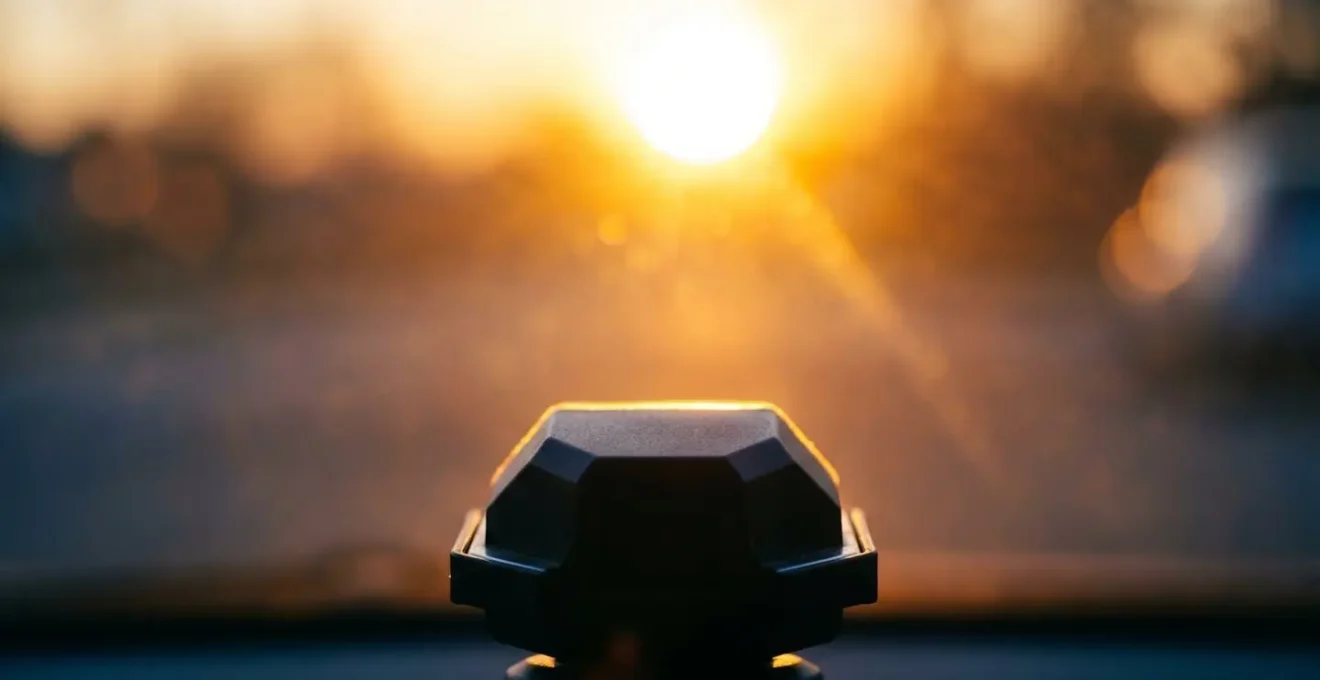
The severity of this issue is directly tied to the wavelength of light the LiDAR system uses. Most affordable, mass-market LiDARs operate at a wavelength of 905 nanometers (nm). Unfortunately, the sun emits a great deal of energy in this part of the spectrum. As a technical analysis points out, more advanced and expensive systems use a different wavelength.
The sun is a massive source of infrared radiation, especially in the 905nm spectrum used by most affordable LiDARs. The sun’s radiation is significantly weaker at 1550nm, making these sensors inherently more resistant to sun glare.
– Technical analysis from One Finite Planet, AI + Self-Driving Car Sensors Explained: LIDAR vs Radar, Cameras & Ultrasonic
This is why 1550nm LiDAR is considered superior for sun glare immunity. Operating in this band is also safer for the human eye, allowing for higher-power lasers that can achieve longer range. However, the components for 1550nm systems are traditionally more expensive, presenting a trade-off between cost and all-weather performance. For a system relying on 905nm LiDAR, driving directly into a low-angle sun must be considered a potential exclusion within its Operational Design Domain (ODD).
Where to Mount Aftermarket Sensors for Maximum Field of View?
For developers, researchers, or enthusiasts retrofitting vehicles with autonomous driving hardware, sensor placement is a critical engineering decision with significant trade-offs. The optimal mounting location depends entirely on the intended use case, and there is no single « best » position. The goal is to maximize the field of view (FoV) for the primary operational environment while minimizing exposure to the elements and interference with existing vehicle systems. Incorrect placement can render a high-quality sensor ineffective.
A roof-mounted sensor, for example, offers an unparalleled 360° view, making it ideal for urban robotaxi applications requiring a full awareness of cross-traffic, pedestrians, and cyclists. However, this position increases the vehicle’s height and exposes the expensive sensor to the full force of weather and potential impacts. Conversely, mounting sensors within the grille or behind the windshield provides protection and a clean aesthetic, but it inherently limits the FoV and introduces new problems like signal attenuation through glass or « clutter » from road splash. Each choice requires careful consideration of the sensor’s specific function and limitations.
Action Plan: Key Sensor Mounting Protocols
- Prioritize Position by Use Case: Select a roof mount for 360° coverage (robotaxis), a grille/windshield mount for highway-focused forward vision, or fender mounts for low-speed urban navigation and blind-spot monitoring.
- Execute Precise Extrinsic Calibration: Use specialized targets to define the sensor’s exact position and orientation relative to the vehicle’s axes. A mere 1-degree angular error can result in positional errors of several meters at a 100-meter distance, making path planning unsafe.
- Account for Signal Attenuation: Factor in a 15-20% signal loss for sensors mounted behind a windshield due to glass absorption and potential wiper blockage. For grille-mounted sensors, anticipate data clutter from splash-back in wet conditions.
- Verify No OEM Sensor Interference: Ensure aftermarket sensors, particularly those in grille areas, do not obstruct or interfere with the vehicle’s factory-installed safety sensors (e.g., radar for ACC/AEB) to avoid voiding the warranty and creating liability issues.
- Implement Automated Cleaning Systems: For any sensor mounted in a low, forward-facing position exposed to road debris, integrate a cleaning solution such as fluid jets or air knives to maintain performance.
Ultimately, sensor mounting is a systems-level engineering problem. It requires a holistic approach that balances the need for a clear, unobstructed view with the practical realities of vehicle dynamics, environmental exposure, and integration with existing safety features.
The Investment Mistake That Could Render Your Transport Logistics Obsolete in 10 Years
For the transport and logistics industry, the allure of autonomous trucking is immense, promising increased efficiency, reduced labor costs, and improved safety. However, an investment in Level 4 autonomous systems based on an incomplete understanding of sensor limitations is a catastrophic financial risk. The central mistake is evaluating a technology based on its advertised capabilities rather than its rigorously defined Operational Design Domain (ODD). An ODD specifies the precise conditions—including weather, time of day, road types, and geographic areas—in which the autonomous system is validated to operate safely.
The core of the issue lies in the dramatic performance disparity between sensor types in adverse weather. While LiDAR provides superior spatial resolution in clear conditions, its performance degrades precipitously in rain and fog. In contrast, radar’s longer-wavelength radio waves are largely unaffected. As comparative studies demonstrate, LiDAR performance drops to less than 60% in heavy rain, while radar maintains greater than 95% detection accuracy under the same conditions. A logistics company that invests millions in a fleet of autonomous trucks with an ODD specified for « light rain only » will find its assets functionally useless for significant portions of the year in regions with frequent precipitation, destroying any projected return on investment.
Case Study: The ODD Mismatch in Autonomous Deployments
A comprehensive academic survey of sensor failures in autonomous vehicles highlighted a critical pattern: companies investing in Level 4 systems without exhaustively analyzing their ODD against actual operating routes face systemic failures. The research noted that systems designed with a limited ODD, such as « light rain only, » would be rendered inoperable for large parts of the year in climates like the Pacific Northwest or Northern Europe. This mismatch between the system’s validated capabilities and the operational reality of a logistics route turns a technological asset into a stranded one, unable to generate revenue whenever the weather turns sour.
Therefore, the crucial due diligence for any investor or fleet manager is not to ask « Does it have LiDAR? » but rather « What are the precise, validated boundaries of the system’s ODD, and how do those boundaries align with the weather patterns of my intended operational routes? » Ignoring this question is an invitation to obsolescence.
V2I Communication: How Do Smart Signs « Talk » to Self-Driving Cars?
When a vehicle’s onboard sensors are compromised by torrential rain, fog, or snow, how can it continue to navigate safely? The answer may lie outside the vehicle itself, in its ability to communicate with the surrounding infrastructure. This is the principle of Vehicle-to-Infrastructure (V2I) communication, a technology that allows vehicles and infrastructure elements like traffic signals, work zones, and smart signs to exchange critical safety information wirelessly.
V2I acts as a crucial layer of redundancy. It provides data that is not dependent on line-of-sight optical or radar sensors, offering a ground truth that can augment or even override a vehicle’s potentially flawed perception. As experts in the field note, this provides a vital fallback when a car’s own sensors are blinded. According to the V2I Deployment Coalition’s technical framework, this communication provides a direct digital feed of essential information.
The process works through standardized digital messages. A « smart » electronic sign at a work zone, for instance, doesn’t just display a warning; it continuously broadcasts a Traveler Information Message (TIM). This digital message contains structured data, including the type of event (e.g., « lane closure ahead »), its precise GPS coordinates, the affected lanes, and a recommended safe speed. An approaching autonomous vehicle receives this message via a dedicated short-range communication (DSRC) or cellular (C-V2X) radio, instantly gaining situational awareness that its weather-impaired LiDAR or cameras might have missed. Similarly, a smart traffic light can broadcast Signal Phase and Timing (SPaT) messages, telling the vehicle exactly when the light will turn green, yellow, or red, enabling smoother and safer intersection passage.
V2I is not a replacement for onboard sensors but a powerful complementary data source. It provides deterministic, unambiguous information that can help an autonomous system make safer decisions when its own perception of the world is uncertain.
Key Takeaways
- LiDAR’s performance significantly degrades in adverse weather, with measurable drops in range and point cloud density that can create dangerous blind spots.
- The safety and viability of an autonomous system are not defined by its hardware but by its validated Operational Design Domain (ODD), which must account for these limitations.
- Hardware durability (solid-state vs. mechanical) and the integrity of system maintenance, particularly sensor cleaning and calibration, are critical, non-negotiable engineering challenges.
Why Your Lane Keep Assist Pulls to the Right After Windshield Replacement?
While much of the focus is on advanced sensors like LiDAR, the integrity of a vehicle’s entire Advanced Driver-Assistance System (ADAS) suite depends on something as seemingly simple as its calibration. A common and disorienting issue owners face after a windshield replacement is a Lane Keep Assist system that no longer tracks straight. This problem is a direct result of improper or incomplete sensor recalibration, and it perfectly illustrates the sensitive, integrated nature of modern vehicle safety systems.
The forward-facing camera, which is the primary sensor for Lane Keep Assist and other features like Automatic Emergency Braking, is typically mounted to the windshield. When the windshield is replaced, the camera’s position and viewing angle are altered by fractions of a millimeter or degree. While imperceptible to the eye, this tiny shift creates a significant positional error when projected hundreds of feet down the road. The system, believing it is still perfectly aligned, now « sees » the lane markings in the wrong place, causing it to steer the vehicle incorrectly.
Correcting this requires a precise two-part process known as extrinsic calibration. First, a static calibration is performed in a workshop using specialized targets placed at exact distances and heights, resetting the camera’s baseline. Second, a dynamic calibration is performed on the road, where the vehicle is driven at a specific speed on well-marked lanes to allow the system to fine-tune its parameters in a real-world environment. Shops that skip the dynamic step, or use aftermarket glass with slightly different optical properties or thickness than the OEM specification, will induce persistent errors that compromise safety. Every camera-dependent system—Lane Keep, AEB, Traffic Sign Recognition, and Adaptive Cruise Control—must be verified post-replacement to ensure it performs to manufacturer specifications.
This single example demonstrates that an autonomous or semi-autonomous system is only as reliable as its weakest link. A multi-thousand-dollar sensor suite can be rendered unsafe by a ten-dollar mistake in a routine service procedure. It highlights the absolute necessity of rigorous, end-to-end calibration and validation for every component in the safety chain.
Before investing in or relying on an autonomous system, demand access to its validated Operational Design Domain and query its performance limitations in environmental conditions relevant to your use case. True safety lies not in the promise of the technology, but in a transparent and rigorous understanding of its boundaries.