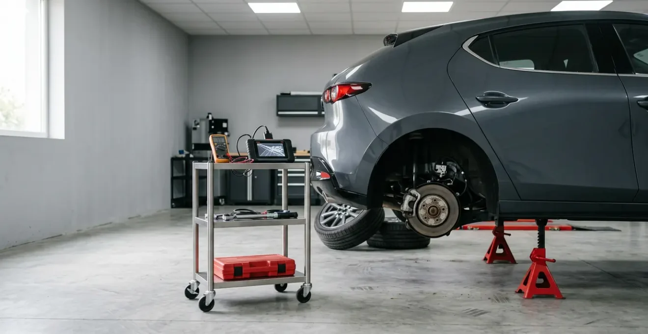
In summary:
- False ABS activation at low speeds is not a random glitch but a symptom of a poor signal-to-noise ratio from a wheel speed sensor.
- The root cause is often physical interference (rust, debris) or a damaged reluctor ring creating a « noisy » signal the ABS module misinterprets as a locked wheel.
- Diagnosis requires moving beyond basic code reading to visually inspecting sensors and rings, and using the correct tools to analyze the live signal quality.
- Neglecting this fault compromises your entire suite of safety systems, including ESP and collision mitigation.
That unnerving, grinding pulse from the brake pedal as you gently glide into a parking space is more than just a nuisance; it’s a critical diagnostic clue. It’s the Anti-lock Braking System (ABS) activating when it shouldn’t, a sign that your vehicle’s safety net is malfunctioning. Many drivers are told the cause is simply a « dirty wheel speed sensor, » but this explanation is dangerously simplistic. It ignores the fundamental reason for the failure: a breakdown in communication within the vehicle’s braking nervous system.
The problem is rarely the ABS control module itself. Instead, the module is receiving a corrupted message—a signal so full of « noise » that it misinterprets a slowly rotating wheel as one that is locked solid. This false activation on dry, high-grip surfaces is a classic symptom of a compromised wheel speed sensor signal. The key to a successful repair is not to just replace parts, but to adopt a diagnostician’s mindset: you must become a signal integrity expert.
But what turns a clean, precise signal into unintelligible noise? The causes range from simple metallic debris to microscopic cracks in sensor rings and the insidious, silent corrosion caused by old brake fluid. Understanding this « signal-to-noise » problem is the first step toward a correct and permanent fix. This guide will move beyond guesswork, providing a systematic approach to pinpoint the true source of the failure, ensuring your vehicle’s most important safety system performs exactly as intended, and only when needed.
To properly diagnose this fault, we will explore the system’s logic, common failure points, and the tools required for an accurate assessment. This structured approach will help you understand the ‘why’ behind the failure, not just the ‘what’.
Summary: Troubleshooting False ABS Activation
- Why ABS Might Increase Your Stopping Distance on Gravel or Snow?
- How to Clean Magnetic Speed Sensors Without Damaging the Ring?
- Active vs. Passive Sensors: Which Type Is harder to Diagnose with a Multimeter?
- The Brake Fluid Mistake That Corrodes Your $800 ABS Modulator
- When to Replace a Rusted Reluctor Ring: Visual Signs of Impending Failure?
- The Wheel Speed Sensor Issue That Disables Your ESP
- Bluetooth vs. Handheld Scanners: Which Is Better for ABS and Airbag Codes?
- ESP on Black Ice: Will It Save You or Do You Need to Steer?
Why ABS Might Increase Your Stopping Distance on Gravel or Snow?
Before diagnosing a fault, it’s crucial to understand the system’s intended function. On high-friction surfaces like dry pavement, ABS consistently shortens stopping distances by preventing wheel lock-up and maintaining steering control. However, on loose or deformable surfaces like gravel, snow, or sand, the physics change dramatically. A locked, non-rotating tire can dig into the loose material, building a wedge of gravel or snow in front of it. This « plowing » effect creates significant drag and can, in some cases, stop the vehicle shorter than an ABS-managed stop.
The ABS, by design, prevents this plowing. It meticulously modulates brake pressure to keep the wheel rotating at the threshold of grip, which is extremely low on these surfaces. By preventing the wheel from locking, it also prevents the formation of that helpful wedge. This is why research shows that on loose surfaces such as gravel, stopping distances can increase significantly compared to a non-ABS vehicle. The system is prioritizing its primary mission: maintaining steering control at all costs, even if it means sacrificing some straight-line stopping performance in specific, low-grip scenarios. Understanding this trade-off is key to appreciating why the system is so sensitive to wheel speed signals.
The effectiveness of ABS is entirely dependent on the coefficient of friction between the tire and the road. This table illustrates how the system’s behavior changes across different surfaces.
| Surface Type | Coefficient of Friction (μ) | ABS Behavior | Stopping Characteristics |
|---|---|---|---|
| Dry Asphalt | 0.8 – 1.0 | Optimal pulse modulation at 10-20% slip | Shortest distance, full steering control |
| Wet Asphalt | 0.5 – 0.7 | Increased modulation frequency | Moderate distance increase, steering maintained |
| Snow (Packed) | 0.2 – 0.3 | Continuous cycling, prevents wheel lock | Longer distance vs. locked plowing wheel |
| Gravel (Loose) | 0.3 – 0.4 | Prevents wedge formation | Can increase distance vs. locked wheel buildup |
| Ice | 0.1 – 0.2 | Minimal traction optimization possible | Maximum distance, steering control priority |
How to Clean Magnetic Speed Sensors Without Damaging the Ring?
The most common cause of false low-speed ABS activation is signal interference at the sensor tip. The sensor is a magnet that reads the passing teeth of a reluctor ring. Over time, it accumulates a paste of metallic brake dust, road grime, and rust particles. This buildup physically obstructs the magnetic field, weakening the signal sent to the ABS module. At high speeds, the signal frequency is strong enough to punch through the « noise, » but as the vehicle slows to a near stop, the weak, low-frequency signal becomes indistinguishable from a zero-speed (locked wheel) signal. The ABS module, seeing a locked wheel, does its job and activates the pump.
Cleaning the sensor is a valid first diagnostic step, but it must be done with surgical precision to avoid causing more damage. Aggressive scraping or using the wrong chemicals can damage the sensor’s delicate tip or the reluctor ring itself. A metal brush, for example, can scratch the ring’s teeth, creating a new source of signal interference. Spraying cleaner directly into the sensor bore can wash debris further into the hub assembly. The goal is careful removal of debris, not a high-pressure blast.

As the image shows, the buildup can be substantial. Restoring the clear communication channel between the sensor and the ring is paramount. Following a precise, non-destructive procedure is the only way to ensure the cleaning process solves the problem instead of creating a new one. This requires patience and the right tools.
Action plan: Safe Speed Sensor Cleaning Procedure
- Use compressed air from 6+ inches distance to blow away loose debris without damaging sensor tip.
- Apply brake cleaner or electronic parts cleaner to a lint-free cloth, never spray directly on sensor.
- Gently wipe sensor tip with soft-bristle brush (like a toothbrush) in a circular motion; avoid metal brushes.
- Use a plastic or wooden pick to carefully scrape debris from reluctor ring teeth through the sensor hole.
- Clean the sensor bore with brake cleaner on a cloth before reinstallation to remove accumulated rust.
- Apply dielectric grease to the sensor O-ring ONLY (not the sensor tip) to prevent future water ingress.
- Torque the retaining bolt to the manufacturer’s specification (typically 8 Nm) to avoid cracking the plastic housing.
Active vs. Passive Sensors: Which Type Is harder to Diagnose with a Multimeter?
The inability to diagnose a sensor is a common pitfall for many technicians. The issue often lies in not knowing which type of sensor they are dealing with: active or passive. A multimeter, the go-to tool for basic electrical checks, is effective for passive sensors but is not only useless but potentially damaging to active sensors. A passive sensor is a simple variable reluctance device—a magnet wrapped in a coil of wire. As the metal teeth of the reluctor ring pass by, they generate a fluctuating AC voltage (a sine wave). A technician can measure the coil’s resistance with a multimeter to check for continuity. If it’s within spec and not an open circuit, it’s likely functional.
Active sensors, however, are far more complex. They are solid-state Hall effect or magneto-resistive sensors that require a power supply from the ABS module to operate. They contain internal circuitry and produce a clean, digital DC square wave signal. Trying to measure resistance on an active sensor is futile; you’re measuring the resistance of a complex integrated circuit, not a simple coil. Worse, it can send voltage from the multimeter into the sensor’s sensitive electronics, permanently damaging it. This is why according to automotive diagnostic specialists, active sensors cannot be reliably tested with a multimeter.
Case Study: Active Sensor Misdiagnosis with Multimeter Testing
A diagnostic scenario demonstrates why multimeter resistance testing damages active sensors: If supply voltage is missing due to a fault and a technician assumes the sensor is passive and performs a resistance check, they can damage a perfectly good active sensor, creating two faults instead of one. The resistance reading can show normal values even when the sensor’s digital signal processing circuitry is completely failed, leading to wasted part replacement. The only reliable method to test an active sensor is with an oscilloscope or a high-end scan tool to visualize its square wave output while the wheel is spinning. This confirms the sensor is powered, processing, and sending a clear signal.
The Brake Fluid Mistake That Corrodes Your $800 ABS Modulator
While external debris causes signal « noise, » an internal, chemical process can cause catastrophic hardware failure. Brake fluid is hygroscopic, meaning it absorbs moisture from the atmosphere. In fact, studies show that brake fluid will generally absorb 1% or more moisture by volume each year. This water contamination has two devastating effects on the braking system. First, it drastically lowers the fluid’s boiling point, increasing the risk of a soft pedal and complete brake failure under heavy use. Second, and more relevant to ABS faults, it leads to internal corrosion.
The moisture neutralizes the corrosion-inhibiting additives in the fluid. Once these inhibitors are depleted, the water begins to rust the system from the inside out. This corrosion attacks everything from the master cylinder to the caliper pistons. Most critically, it attacks the ABS hydraulic control unit (HCU) or modulator. This is an incredibly complex and expensive component, containing a maze of tiny passages and a series of solenoid-operated valves that pulse tens of times per second. Even microscopic rust particles can cause these delicate valves to seize, leading to a range of problems from a permanently lit ABS light to the exact low-speed activation issue we’re diagnosing. Flushing brake fluid every two years is not an upsell; it’s the single most important preventative maintenance task to protect the heart of your ABS system.
As the Mighty Auto Parts Technical Division notes in its « Brake Fluid Facts » bulletin: « Moisture in the system depletes the corrosion inhibitors in the fluid, resulting in damage to the internal components. Caliper bores, wheel cylinders, the master cylinder and costly ABS components may become pitted, resulting in sticking or binding components and seal leakage. » Verifying fluid condition should be a standard part of any brake system diagnosis. Simple test strips that measure copper content (a sign of internal corrosion) or a digital moisture tester can provide an immediate, quantitative assessment of the fluid’s health.
When to Replace a Rusted Reluctor Ring: Visual Signs of Impending Failure?
The reluctor ring (or tone ring) is the other half of the wheel speed sensor system. It’s a simple-looking toothed wheel, but its physical integrity is paramount. The ABS module calculates wheel speed based on the frequency of the teeth passing the sensor. For this to work, every tooth and every gap between them must be identical. When rust attacks a reluctor ring, it can cause two types of problems with very different consequences.
The first is simple surface rust. This is often cosmetic and, while not ideal, may not significantly interfere with the sensor’s ability to read the teeth. The second, far more sinister problem is « rust jacking. » This occurs when rust forms under the ring or swells between the teeth, physically distorting them. It can crack a pressed-on ring, causing it to wobble, or it can fill the gaps between the teeth. This distortion changes the distance between the tooth and the sensor as the wheel rotates, or it changes the perceived shape of the tooth. The result is a corrupted signal. The sensor’s output waveform becomes erratic, with some peaks lower than others. At low speeds, one of these weak peaks can drop below the module’s detection threshold, fooling it into thinking the wheel has stopped.

Case Study: Reluctor Ring Damage Causing Low-Speed ABS Activation
A PicoAuto diagnostic case study perfectly illustrates this failure. A technician investigating low-speed ABS activation found the root cause was not a faulty sensor, but damage to the reluctor ring. During previous repair work on a wheel hub, a few teeth on the ring had been accidentally impacted, creating shiny, slightly deformed spots. Using an oscilloscope, the technician could see that these damaged teeth generated a significantly weaker signal (lower electromagnetic force) compared to the healthy teeth. At 10 mph, the signal was weak but readable. However, as the vehicle slowed to below 5 mph for a stop, the signal from the damaged teeth became so faint that it dropped off the ECU’s radar. The ECU interpreted this complete loss of signal as instantaneous wheel lock-up and triggered the ABS pump, creating the exact symptom the customer described. This confirms that even minor, barely visible damage to the ring is enough to cause a major fault.
The Wheel Speed Sensor Issue That Disables Your ESP
A faulty wheel speed sensor signal does not just affect the anti-lock braking system; it triggers a cascade of failures across a wide range of modern vehicle safety and convenience features. The ABS forms the foundation layer upon which numerous other systems are built. The four wheel speed sensors are the primary inputs for vehicle speed, and when one of them provides erratic or missing data, the vehicle’s central computer can no longer trust its perception of what the wheels are doing. In the name of safety, it begins to systematically shut down any system that relies on that data.
The most critical of these is the Electronic Stability Program (ESP) or Traction Control System (TCS). These systems work by comparing the driver’s steering input with the vehicle’s actual rotation (measured by a yaw sensor) and individual wheel speeds. If a wheel is spinning under acceleration (traction control) or if the car is starting to slide sideways (stability control), the system can apply the brake to an individual wheel to bring the vehicle back in line. Without reliable data from all four wheels, the ESP module cannot make these critical calculations and is completely deactivated. This means that a single, inexpensive sensor fault can disable the one system most likely to save you from a loss-of-control accident.
The domino effect doesn’t stop there. Here are some of the other key safety systems that are typically disabled by a single wheel speed sensor fault:
- Electronic Stability Control (ESP): The primary stability system is completely deactivated when a wheel speed signal is inconsistent or lost.
- Traction Control System (TCS): Cannot function without accurate wheel speed data from all four sensors to detect wheel spin.
- Adaptive Cruise Control: The system disables as it relies on wheel speed sensors to verify vehicle motion and calculate following distance.
- Collision Mitigation Braking: Emergency braking assistance is often deactivated due to the inability to calculate accurate vehicle deceleration rates.
- Hill Start Assist: Requires wheel speed sensor confirmation that the vehicle is stationary before activation.
- Automatic AWD Torque Distribution: Cannot reliably detect wheel slip to redistribute power between the axles.
Bluetooth vs. Handheld Scanners: Which Is Better for ABS and Airbag Codes?
To diagnose ABS faults effectively, you need a tool that can communicate with the ABS module. Basic, entry-level code readers often only access the powertrain control module (PCM), showing « P-codes » for engine and emissions issues. ABS, airbag (SRS), and other chassis systems generate their own codes (« C-codes » and « B-codes ») that these basic readers cannot see. For ABS diagnostics, you need a scan tool with more advanced capabilities, and the choice often comes down to a Bluetooth dongle paired with a smartphone app or a dedicated handheld scanner.
Bluetooth dongles are affordable and convenient. For a moderate price, they provide access to ABS codes, allowing you to read and clear faults. Many also offer some form of live data, which is a step in the right direction. However, they often have limitations in how they display that data, perhaps only showing one sensor at a time, making it difficult to compare wheel speeds directly. They are an excellent starting point for a DIYer to confirm which corner has the fault.
Dedicated handheld scanners represent the next level. While more expensive, their key advantage for ABS diagnosis is live data graphing. A good handheld unit can display the speed of all four wheels simultaneously on a single graph. This is the single most powerful diagnostic function. By watching the graph as you drive, you can instantly see if one sensor’s signal drops out, becomes erratic, or lags behind the others as you slow to a stop. It turns a guessing game into a certainty. For any serious DIYer or aspiring professional, the ability to visually confirm a signal failure makes a handheld unit the superior choice.
This table breaks down the options for different user needs and budgets when diagnosing ABS faults.
| Scanner Type | Live Data Graphing | ABS/SRS Support | Typical Price Range | Best For |
|---|---|---|---|---|
| Bluetooth Dongle (OBDLink, BlueDriver) | Basic single-parameter view | Read/clear C-codes and B-codes | $100 – $150 | Casual User: Code reading and basic diagnostics |
| Handheld Scanner (Autel, Foxwell) | Multi-channel graphing, 4 wheels simultaneous | Full ABS/SRS with PIDs | $200 – $400 | Serious DIYer: Visual confirmation of sensor dropout |
| Bi-directional Scanner (Launch, Snap-on) | Advanced graphing plus data logging | Active testing (cycle ABS pump/valves) | $800+ | Aspiring Pro: Component activation and bleeding procedures |
Key takeaways
- Low-speed ABS activation is a signal integrity problem, not just a broken part.
- Diagnosis must focus on identifying sources of signal « noise, » such as debris, corrosion, or physical damage to sensor components.
- Using the right tools is non-negotiable; a multimeter is insufficient for modern active sensors, and a scan tool with live data graphing is essential for efficient diagnosis.
ESP on Black Ice: Will It Save You or Do You Need to Steer?
After diving deep into the technical causes of sensor failures, it’s crucial to return to a fundamental reality: electronic safety systems are aids, not miracle workers. Understanding their limitations is as important as maintaining them. Whether it’s ABS or the more advanced Electronic Stability Program (ESP), these systems operate within the laws of physics. Their entire purpose is to optimize the available traction between the tire and the road surface.
On a surface like black ice, the available traction is nearly zero. An ESP system can’t create grip where none exists. If all four wheels are sliding with no purchase on the road, the system has nothing to work with. It can try to brake individual wheels, but if those wheels have no grip, the braking force will have no effect on the vehicle’s trajectory. This is where driver input becomes the system’s last, best hope. The ESP system is designed to help the car follow the driver’s intended path, which it determines from the steering angle sensor.
If you’re in a slide, looking and steering where you want to go gives the ESP module a target. It will do everything in its power, using every ounce of available traction, to make the car go there. If the driver panics and doesn’t provide smooth, deliberate steering input, the system is left without a goal. It’s a partnership between driver and machine. The technology is there to enhance a skilled driver’s control, not to replace it.
ESP can’t create grip; it only optimizes the available traction. It requires driver input to work. The system brakes individual wheels to help the car follow the driver’s intended path.
– Brake & Front End Magazine Technical Staff, False ABS, ESC Activation Causes And Cures
Adopting a proactive and diagnostic approach is the only way to ensure the long-term reliability and safety of your vehicle’s braking system. Begin by assessing the health of your brake fluid and investing in a scan tool that can provide the data you need to see the problem, not just guess at it.