Steering wobble is a critical safety warning from your car’s chassis, not a simple tire issue.
- The « clunk » you hear is often a ball joint on the verge of separation, risking total loss of steering.
- The metallurgy of cheap parts (cast vs. forged) is a primary cause of sudden, catastrophic failure under stress.
- Replacing parts in a strategic order is the key to avoiding double labor costs and achieving a lasting repair.
Recommendation: Prioritize replacing critical safety components like ball joints and tie rods first, even on a tight budget, to immediately restore vehicle safety.
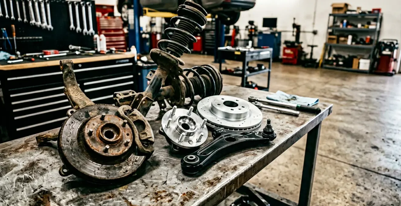
That unnerving vibration in your steering wheel, especially on a 7 to 10-year-old vehicle, is more than just an annoyance. It’s a direct message from your car’s chassis, and ignoring it can have severe consequences. Most drivers immediately suspect the common culprits: unbalanced tires or a bad alignment. While these issues can cause vibrations, they are often just symptoms of a deeper, more dangerous problem. When a vehicle with years of service starts to feel loose, vague, or develops a persistent wobble, the root cause almost always lies in the fatigue and failure of critical suspension and steering components.
Simply balancing tires is like taking a painkiller for a broken bone; it masks the symptom without addressing the underlying fracture. The real solution—and the path to restoring that safe, « new car » feel—is to understand what is actually failing. This involves looking at the material science of the parts themselves, from the way a cheap tie rod is manufactured to the type of rubber used in its bushings. A true, lasting repair isn’t about chasing symptoms; it’s about a strategic restoration of the chassis.
This guide will take you beyond the tire shop’s surface-level advice. We will diagnose the true mechanical culprits behind steering wobble, explore the engineering differences between quality and inferior parts, and lay out a strategic replacement plan. You will learn how to prioritize repairs to maximize safety and avoid paying for the same labor twice, putting a permanent fix well within a reasonable budget.
To help you navigate this essential topic, this article is structured to build your understanding from diagnosis to strategic repair. The following summary outlines the key areas we will cover, allowing you to pinpoint the information most relevant to your vehicle’s symptoms.
Summary: A Strategic Guide to Curing Steering Wobble
- Why Ignoring That « Clunk » Over Bumps Could Lead to Wheel Separation?
- Stamped Steel vs. Aluminum Control Arms: Which Withstands Potholes Better?
- Polyurethane vs. Rubber Bushings: Which Is Right for a Comfortable Daily Driver?
- The Metallurgy Flaw in Cheap Tie Rods That Snaps Under Emergency Braking
- In What Order Should You Replace Chassis Parts to Avoid Double Labor Costs?
- Why Saving 5 lbs Per Wheel Feels Like Adding 20 Horsepower?
- How to Recalibrate Ride Height Sensors if Your Car Leans to One Side?
- How to Fix « Suspension Fault » Errors Without Replacing the Entire Shock Absorber?
Why Ignoring That « Clunk » Over Bumps Could Lead to Wheel Separation?
That distinct « clunk » or popping sound your car makes when going over bumps is one of the most serious warning signs your suspension can give you. It often indicates a severely worn ball joint, the critical pivot point that connects your wheel hub to the suspension control arm. When a ball joint is healthy, its internal stud and socket are held in tight tolerance. As it wears, this tolerance loosens, allowing the stud to knock around inside the housing—creating the clunking noise. This isn’t just a noise issue; it’s a direct precursor to catastrophic failure.
The progression from a simple clunk to complete failure can be dangerously swift. Initially, you might only feel a slight steering wobble or hear the noise over large bumps. However, as wear accelerates, the wobble can become violent, especially after hitting a pothole at highway speeds. The final stage is wheel separation. This occurs when the ball joint stud completely pulls out of its socket. The suspension collapses, the wheel tucks inward at an extreme angle, and you experience an instantaneous and total loss of steering control. This scenario is especially high-risk in regions with harsh weather, as recent data shows a 27% higher failure rate for ball joints in extreme climates where salt and moisture accelerate wear.
Treating a clunking sound as a minor annoyance is a gamble with your safety. It’s the final audible warning before the potential for complete structural failure of a cornerstone of your vehicle’s suspension system. Addressing it promptly is not a matter of comfort, but of fundamental vehicle control and accident prevention.
Stamped Steel vs. Aluminum Control Arms: Which Withstands Potholes Better?
When replacing suspension parts, the control arm is a major component to consider, and the material it’s made from—typically stamped steel or forged aluminum—has a profound impact on durability and safety. For a daily driver that frequently encounters rough roads and potholes, understanding the difference is crucial. Stamped steel is the traditional, cost-effective choice. Its primary advantage in a high-impact scenario is its failure mode: it tends to bend and deform rather than break. This ductility can be a lifesaver, as a bent control arm may still allow you to « limp home » at a low speed, maintaining some level of vehicle control.
In contrast, forged aluminum control arms are significantly lighter and offer superior corrosion resistance. This weight savings improves handling and suspension response (a topic we’ll explore further). However, their disadvantage lies in their brittleness compared to steel. Under an extreme impact, such as hitting a severe pothole, an aluminum arm is more likely to fracture completely. This results in an immediate, non-drivable failure, similar to a separated ball joint.
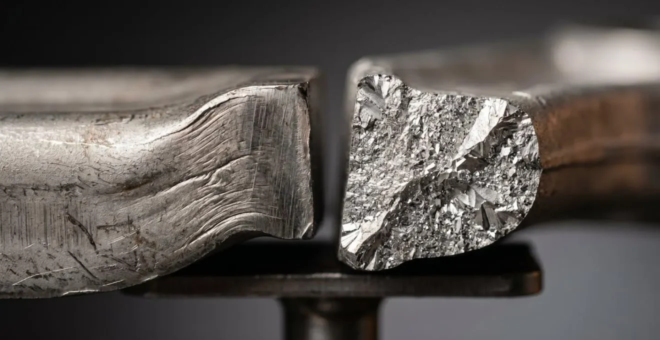
The choice depends on your priorities. For a vehicle in a region with poor road quality, the predictable bending behavior of stamped steel offers a higher margin of safety against sudden failure. For performance-oriented drivers on well-maintained roads, the handling benefits of lightweight aluminum may be worth the risk of brittle fracture.
This table breaks down the key differences to help you make an informed decision based on your driving environment and priorities. Sourcing this data from a detailed performance matrix provides a clear, fact-based comparison.
| Characteristic | Stamped Steel | Forged Aluminum |
|---|---|---|
| Failure Mode | Bends under extreme impact, allows ‘limp home’ capability | May fracture completely, causing immediate non-drivable failure |
| Weight | 14.7 lbs (typical lower control arm) | 7 lbs (typical lower control arm – 53% lighter) |
| Corrosion Resistance | Requires coating; susceptible to rust in salt environments | Natural oxide layer prevents rusting |
| Durability in Pothole Regions | Predictable bending behavior; high impact tolerance | Risk of brittle fracture; better for maintained roads |
| Cost | Budget-friendly | Premium pricing |
Polyurethane vs. Rubber Bushings: Which Is Right for a Comfortable Daily Driver?
Bushings are the unsung heroes of your suspension, acting as rubber cushions that isolate vibration and absorb impacts at every connection point. When they wear out, your steering can feel sloppy and you’ll hear more road noise. When replacing them, you have two main choices: traditional rubber or performance-oriented polyurethane. For a comfortable daily driver, the choice is not as simple as « which is better. » It’s about understanding the trade-offs between comfort and performance.
Original Equipment (OE) bushings are made of a soft rubber compound. Their purpose is to provide maximum vibration-damping and a quiet, compliant ride. This softness, however, allows for more suspension flex under load, which can translate to less precise handling. Polyurethane bushings, on the other hand, are a much harder material. Durometer testing shows that while stock OE rubber measures a soft 50-60A on the hardness scale, even « street » polyurethane comes in at a much firmer 75-85A. This stiffness drastically reduces suspension deflection, resulting in sharper steering response and more stable handling.
However, this firmness comes at a cost. Polyurethane transmits far more noise, vibration, and harshness (NVH) into the cabin, making the ride feel significantly stiffer and less comfortable. More importantly for a daily driver, polyurethane bushings require regular maintenance to prevent them from squeaking loudly. Unlike rubber, which is bonded to its metal sleeve, polyurethane rotates directly against the metal. Without proper lubrication, this movement creates a persistent, irritating squeak. Therefore, if you prioritize a quiet, comfortable ride over track-day performance, sticking with high-quality rubber bushings is almost always the right choice for a daily-driven vehicle.
The Metallurgy Flaw in Cheap Tie Rods That Snaps Under Emergency Braking
Not all replacement parts are created equal, and nowhere is this truer or more critical than with steering components like tie rods. A tie rod connects your steering rack to the wheel, and its failure means a complete loss of steering for that wheel. The safety difference between a quality part and a cheap one lies in its internal metallurgy—specifically, whether it’s forged or cast.
High-quality, OEM-equivalent tie rods are typically forged. This process involves heating a billet of steel and hammering it into shape. This aligns the metal’s internal grain structure, much like twisting individual fibers into a strong steel cable. This aligned grain makes the part incredibly resilient, with the ability to stretch or elongate significantly before breaking. In contrast, cheap aftermarket parts are often cast. This involves pouring molten metal into a mold. The resulting grain structure is random and non-uniform, similar to concrete—strong under compression but brittle under tension. Critically, the casting process can introduce microscopic air bubbles, or porosity, which remain hidden within the part.

These hidden voids act as stress risers. Under the immense load of an emergency braking maneuver or a sudden swerve, a microcrack can nucleate at one of these voids and propagate through the brittle material instantaneously. The part snaps with zero warning. As failure analysis of forged vs. cast metallurgy shows, a forged part’s manufacturing process inherently tests its integrity, as any major flaw would be revealed by the hammer blows. A casting defect remains a hidden time bomb. Choosing a part based on price alone means you could be unknowingly installing a component with a built-in flaw, designed to fail under the exact emergency conditions where you need it most.
In What Order Should You Replace Chassis Parts to Avoid Double Labor Costs?
One of the biggest concerns when facing a suspension overhaul is the cost, a significant portion of which is labor. The key to staying under a budget—like the $600 mentioned in the title—is to work smart by understanding labor overlap. Many suspension repair jobs require the same disassembly steps. By grouping these jobs together in a single session, you avoid paying a mechanic to take the same things apart multiple times.
The most effective strategy is to group components based on shared disassembly and the need for a post-repair alignment. Here’s a logical breakdown:
- Group 1 (Maximum Labor Overlap): The golden trio is the control arm, ball joint, and strut assembly. To replace a control arm, a mechanic must separate the ball joint and often remove the strut. Doing all three at once means you are only paying for one major disassembly session, which can represent up to 90% of the shared labor cost.
- Group 2 (Alignment-Critical): Any component that affects suspension geometry requires a professional wheel alignment afterward. This includes tie rods, control arms, and any related components. If you’re replacing tie rods and know your control arm bushings are worn, do them at the same time to pay for only one alignment.
- Group 3 (Independent Components): Parts like sway bar links and, in many cases, rear shock absorbers can be replaced independently without affecting alignment. These can be scheduled separately as your budget allows without incurring extra costs.
With a limited budget, you have two primary paths. Budget Path A (Safety First) prioritizes the parts whose failure is most catastrophic: ball joints and tie rods. This immediately secures the vehicle’s steering integrity. Budget Path B (Handling First) focuses on control arm bushings and struts to restore ride quality and eliminate the « loose » feeling from worn rubber. Strategically choosing your path and grouping the work is the single most effective way to make a comprehensive suspension repair affordable.
Why Saving 5 lbs Per Wheel Feels Like Adding 20 Horsepower?
When upgrading suspension components, you’ll often see « weight savings » touted as a major benefit, especially with parts like aluminum control arms. This might seem like a minor detail, but reducing weight at the wheels has a disproportionately large effect on both handling and acceleration. This is due to the concept of unsprung weight.
Unsprung weight is the mass of all the components not supported by the car’s springs. This includes the wheels, tires, brakes, and parts of the suspension like control arms and wheel hubs. The lighter this assembly is, the less work the shock absorber has to do to keep the tire pressed firmly against the road surface. When you hit a bump, a lighter wheel assembly can react and change direction much more quickly, allowing the tire to maintain contact with the asphalt. A heavy wheel, by contrast, has more inertia and will tend to bounce in the air for longer, reducing grip and stability.
This is why reducing unsprung weight feels like a significant power boost. A lighter wheel and suspension assembly requires less energy to spin up to speed, so more of the engine’s power goes directly into accelerating the car itself. It’s often said that every 1 pound of unsprung weight saved is equivalent to removing 4-8 pounds of sprung weight (the body of the car). For example, a modern Mustang GT that switches to aluminum control arms can save over 7 pounds per side. On a road course, this translates to dramatically improved handling and steering response because the suspension can manage the wheel’s movement more effectively. You feel this as sharper turn-in, better feedback through the steering wheel, and a car that feels more nimble and eager to accelerate.
How to Recalibrate Ride Height Sensors if Your Car Leans to One Side?
If your vehicle is equipped with an adaptive or air suspension system, replacing parts like control arms can sometimes result in a new problem: the car now leans to one side or displays a « suspension fault » warning. This is often because the ride height sensors need to be recalibrated. These sensors are simple devices—usually a small plastic arm connected to a rheostat—that tell the suspension control module how high each corner of the car is sitting. When you install new parts, you can slightly alter this position, and the system needs to be taught the « new normal. »
Recalibration is a precise process that requires both mechanical and electronic steps. Attempting to do it without the proper procedure will not solve the problem. Here is the correct, step-by-step approach to ensure your car sits level and fault-free after a repair:
- Step 1 – Set Mechanical Zero: Before any electronic adjustments, the foundation must be perfect. Park the car on a completely flat and level surface. All new suspension components must be fully installed and torqued to specification.
- Step 2 – Verify Physical Level: Use a precision level or measure from the center of the wheel to the fender lip on both sides to confirm the vehicle is mechanically level. The sensor only reports the position; the position itself must be physically correct first.
- Step 3 – Access Diagnostic Software: You will need an affordable diagnostic tool capable of accessing the suspension module. Options like VCDS for Volkswagen/Audi, BimmerLink for BMW, or an OBDLink adapter with a manufacturer-specific app (often a total investment under $150) are required.
- Step 4 – Perform Electronic Calibration: Within the diagnostic software, find the suspension control module and look for a function like « Basic Settings » or « Height Sensor Calibration. » Follow the guided procedure to set the « Electronic Zero » point. This tells the computer that the current sensor reading corresponds to the correct, level ride height.
- Step 5 – Test and Verify: After calibration, clear any fault codes and take the vehicle for a drive. Monitor the ride height and check for any returning fault lights. If the lean comes back, re-check your mechanical installation and repeat the calibration.
This procedure syncs the physical reality of your new parts with the electronic brain of your suspension system, resolving leaning issues and clearing persistent fault codes that a simple part swap can’t fix.
Key Takeaways
- A « clunk » over bumps is often a final warning before potential ball joint failure and a complete loss of steering control.
- The manufacturing method of a part (forged vs. cast) and its material (steel vs. aluminum) directly impact your vehicle’s safety and durability in real-world conditions.
- Grouping suspension repairs (e.g., control arm, ball joint, and strut) into a single session can save up to 90% in overlapping labor costs.
How to Fix « Suspension Fault » Errors Without Replacing the Entire Shock Absorber?
Seeing a « Suspension Fault » or « Check Suspension » light on the dash of a car with an adaptive suspension can be daunting, with many shops immediately quoting a replacement of the entire, expensive shock absorber. However, the shock itself is often mechanically sound. The fault frequently lies in the much cheaper and more fragile supporting electronics. Before agreeing to a costly replacement, a systematic diagnostic process that prioritizes the cheapest fixes first can often solve the problem for a fraction of the cost.
The issue could be as simple as a corroded wire or a faulty sensor. By working through a checklist from the easiest and cheapest potential causes to the most complex, you can isolate the true source of the fault. The key is to rule out the simple things before condemning the expensive component. This requires a hands-on inspection of the wiring and connectors that are exposed to the harsh environment underneath your car.

The following checklist provides a logical path for diagnosing these common electronic faults, potentially saving you hundreds or even thousands of dollars.
Your Diagnostic Action Plan: Suspension Faults
- Inspect the Wiring Harness: Check the entire length of the wire from the suspension computer to the shock for breaks, rodent damage, or corrosion. Pay close attention to connectors and areas where the wire bends or is secured to the chassis.
- Test the Ride Height Sensor: Inspect the ride height sensor at the affected corner for physical damage, a disconnected linkage arm, or binding. These simple rheostats are a common failure point and are much cheaper to replace than a shock.
- Clean the Shock Connector: Check the electrical connector at the top of the shock absorber itself. Moisture and dirt often lead to corrosion on the pins. Disconnect it, clean thoroughly with electrical contact cleaner, and apply dielectric grease before reconnecting.
- Diagnose with a Multimeter: Use a basic multimeter to test the resistance of the electronic actuator circuit on the adaptive shock. Compare this value to the factory specification. This test definitively proves whether the fault is in the wiring or the shock’s internal module.
- Consider a Damper Delete Kit: If the diagnostic proves the shock’s electronic module has failed but the shock is still good mechanically, an inexpensive resistor kit can be a solution. This kit « tricks » the computer into thinking the shock is working, clearing the fault code and allowing you to continue using the shock as a standard passive damper.
Don’t let a steering wobble compromise your safety or a warning light intimidate you into an expensive, unnecessary repair. By understanding the true causes of chassis fatigue and approaching diagnostics strategically, you can have an informed conversation with your mechanic. Invest in the quality, forged components and a logical repair plan that will restore your car’s handling, your safety, and your peace of mind on the road.